Overview[]
Prison Architect provides a method to create logic designs through the use of Logic Circuits and Wires. By connecting the basic Logic Circuits in specific ways more interesting and useful designs can be realized. In this article we will discuss the design and function of some of the more interesting designs that can be created.
Clock and Pulse Generator[]
Clock Generator[]

Clock Generator
Many of the logic circuits discussed in the following sections require a clock input. These circuits are referred to as synchronous logic circuits. While a clock signal can be done manually with a power switch connected to a status light, it is more appropriate to create a clock generator to provide the necessary signal.
A clock is nothing more than a repeating signal of Low->High. To create this circuit you need to form a delay that will be used as a feedback to the input of the clock. In Prison Architect this can be achieved with just 3 logic circuits (1 x XOR, 2 x NOT). The pattern used in this article will be 5 logic circuits (1 x XOR, 4 x NOT). The clock is realized by connecting the output of the XOR to the 4 NOT circuits in series. Then the output of the final NOT is connected to the input of the XOR.
Refer to the image of the clock generator to the right. This circuit has a power switch whose output is connected to the status light (you cannot connect the switch directly to the logic circuit). The status light output is connected to the input of the XOR. The XOR output is connected to the first NOT circuit. The rest of the NOT circuits are all connected in series. The final NOT has its output connected to the input of the XOR. The final NOT is also connected to a status light so we can see the result of the circuit.
Pulse Generator[]

Pulse Generator
The pulse generator is a circuit that extends from the clock generator. The key difference is that the pulse generator will generate a short pulse on the rising edge of the clock pulse. This is useful for circuits that require a clock edge to trigger a change (e.g. D-FlipFlops, JK-FlipFlops).
The pulse generator in the image to the right has the familiar clock circuit from above with the addition of a NOT circuit and an AND circuit. The modification is to connect additional outputs of the final NOT circuit of the clock to the NOT and AND circuits. Then connect the output of the new NOT circuit(bottom right) to the to the input of the new AND circuit.
Because it takes more time for the output of the clock to travel through the NOT circuit to the AND circuit then it does for the output of the clock to the AND circuit, there is a brief period of time on the rising edge of the clock where both inputs to the new AND circuit are both true. For this short period of time the output of the new AND circuit is true. You can see this in the image by the fact that the status lamp for the pulse output is on for only a short period of time after the clock output goes high.
Combinational Logic Circuits[]
Multiplexer[]
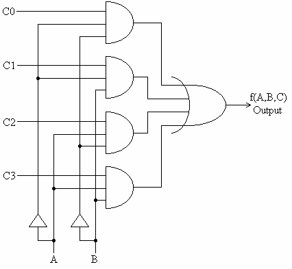
Multiplexer Logic Diagram
A multiplexer is a circuit with multiple inputs and one output. The circuit has a number of control inputs used to map a specified input to the output. The image to the right show the logic diagram for a 4-input multiplexer. The control signals 'A' and 'B' are used to select the input (C0, C1, C2, C3) to map to the output.
The image of the Multiplexer created in Prison Architect shows the operation of a multiplexer where the values for C0, C1, C2, and C3 map to the four power switches in order from top to bottom. The bottom two power switches represent the 'A' and 'B' control inputs. Notice as the inputs 'A' and 'B' cycle through the possible values that the output depends on the value of the input.


Prison Architect Multiplexer
The following table shows the output F based on the values of 'A' and 'B' for both the generic multiplexer and the Prison Architect multiplexer with the input values seen in the image.
| Logic Diagram Multiplexer | Prison Architect Multiplexer | ||||||||||||||||||||||||||||||
|---|---|---|---|---|---|---|---|---|---|---|---|---|---|---|---|---|---|---|---|---|---|---|---|---|---|---|---|---|---|---|---|
|
|
Decoder[]

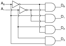
A decoder is a circuit with 'n' number of inputs and 2n outputs. The inputs can be used to select a specific output to be high while all other outputs will remain low. The image to the right shows the logic diagram of a 2-to-4 decoder.


The image of the decoder created in Prison Architect shows the operation of the 2-to-4 decoder. Inputs 'A0' and 'A1' are the two power switches on the left from top to bottom and outputs 'D0' through 'D3' are the status lights on the right from top down. Notice as the values for the inputs counts (in binary) from 0 to 3 the high output cycles from 'D0' through 'D3'.
The following truth table shows the outputs 'D0' through 'D3' based on the values of 'A0' and 'A1'.
| A0 | A1 | D0 | D1 | D2 | D3 |
|---|---|---|---|---|---|
| 0 | 0 | 1 | 0 | 0 | 0 |
| 0 | 1 | 0 | 1 | 0 | 0 |
| 1 | 0 | 0 | 0 | 1 | 0 |
| 1 | 1 | 0 | 0 | 0 | 1 |
Using logic circuits to create a power supply with fail-over[]
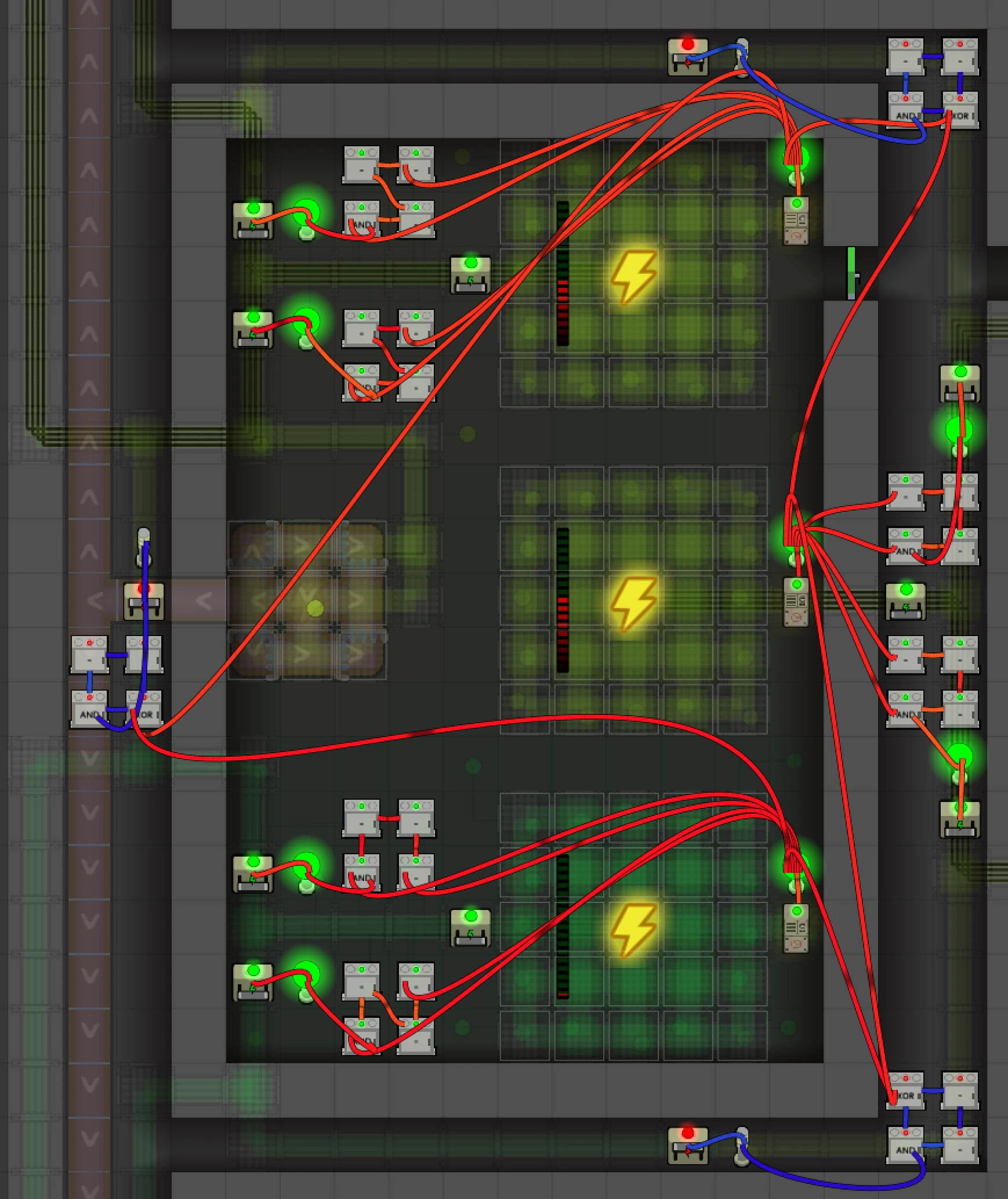
Extending the circuits above, one can create a set of logic circuits that takes the status of a set of generators as input and assigns power networks to the set of online generators. In the picture below, such a set is shown for a combination of 3 generators and 6 power networks. In this setup, when a power generator fails, the other two generators will each take over one network from the failed generator.

The circuits used during normal operation consist of an AND port which is connected directly to the power indicator of the generator and also to a chain of [==] objects, which is also connected to the power indicator. Because it takes some time for the signal to pass through the chain of [==] objects, the signal will switch on with a delay, but switch off directly. This is important to ensure that no grid is powered by 2 generators at the same time (which would result in both generators failing).
The failover circuits are the same, but preceded by an XOR gate that is connected to two generators. If one of the generators fails, the XOR signal will become positive and the failover will kick in. Here a similar delay circuit is used to make sure the other generator takes itself of the grid before the fail-over takes place, to ensure no total failure of the system.